Sunday, March 22, 2015

ESP8266 breakout board

In my previous post, I shared my first experience with ESP8266. Further I wanted try various firmware and try building my own firmware. For this, so much cabling is not good so I set out to prepare a small breakout board which can connect one end with CP210x USB to serial board and another end with ESP-01.

The breakout board will have reset button, GPIO0 ground button, a jumper to ground GPIO0, power selection jumper, a port with 3.3V, GND and GPIO2.

Give below my progress step by step:

1. Schematic


2. PCB Layout (bottom)


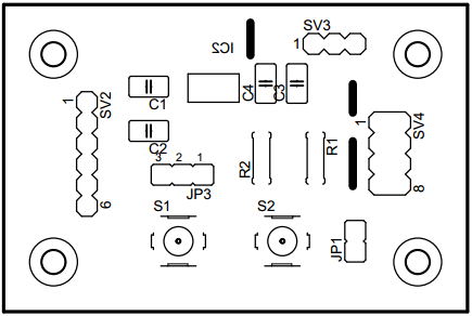
3.Component layout (note the dark 3 lines are for wire jumpers)

4. Assembled board (note 3wire jumpers as it is single side I could not avoid, 117 3.3V regulator is SMD and I do not have it right now so not soldered in bottom side. Later in the input side 10uF capacitor place I put a 2pin header so I can connect to an external regulator PCB module )


5. All boards connected together

6. Working one (note : as I have not soldered 3.3V regulator, still using external regulator module)

7. With 3.3V regulator soldered (during soldering I found out, I did a mistake in AM117 footprint, now I updated schematic and board to v1.1, I did a small track repair to make my v1.0 PCB work)

8. Check github for related files at https://github.com/MohanRenganathan/ESP8266-ESP-01

Saturday, March 21, 2015

Using ESP8266

Around 6 months back I stumbled on ESP8266 while searching for low cost WiFi module. Most of the other WiFi modules costs INR 2000-3000 and adding a WiFi to embedded projects seem to be very costly proposition. So when ESP8266 came in the price range of US$ 3-5, it looked like best of the best thing to happen. But when I looked that time, the documentation was very minimal and even the available ones were in Chinese so temporarily I put my interest on hold thinking let it mature.

As I watched, whole lot of people worked on it, multiple modules came out, so may sites came out hacking it. Even the Chinese supplier started publishing source code and I felt it is right time to play around with it. So I ordered couple of modules (ESP-01, ESP-03, ESP-12) from China. The cost is starting at RMB 13 (INR 130 approx, sellers in India selling it starting from INR 500).

Got the modules in a week time and it is time to play around these modules and I am sharing my experience below. In the below picture the the modules shown are ESP-01, ESP-12 and ESP-03.


It is easy to use ESP-01 as it has headers already soldered. So I used this first to test it out.
  1. As various sites pointed out, I am going to use a USB to Serial converter to connect it to a PC.
  2. I used CP210X based USB to serial converter, fortunately the one I have is giving 3.3V logic level at RX/TX so no issue in connecting it directly to ESP-01, yes some people tried connecting 5V level (say from Arduino) but I would like to stay within spec.
  3. Looks like ESP8266 current consumption is high in the range of 70 to 100mA so need have separate 3.3V source rather than using supply provided by CP210X module (per CP210x datasheet it's built in regulator can give a max of 100mA so do not want stress it). I had a small module which will take 5V input and give 3.3V output and I used the same
  4. Next is to measure the current consumed by whole setup. For this I used small device sold in Chinese sites which can measure Voltage, Current, Power & Charge
  5. The wiring diagram
  6. Below image shows how it all looks when connected together. As seen in the picture the modules current draw varies from 40 to 90mA.


  7. ESP-01 response in a serial terminal, I used Hercules utility, Baud can be anything, I first tried 115200 and it did not work so tried 9600 and it worked. So try different values. As we type in terminal it is sent to ESP-01 and command end is sensed by CR/LF so enable CR/LF and disable Local Echo.