In my previous post, I shared my first experience with ESP8266. Further I wanted try various firmware and try building my own firmware. For this, so much cabling is not good so I set out to prepare a small breakout board which can connect one end with CP210x USB to serial board and another end with ESP-01.
The breakout board will have reset button, GPIO0 ground button, a jumper to ground GPIO0, power selection jumper, a port with 3.3V, GND and GPIO2.
Give below my progress step by step:
1. Schematic

2. PCB Layout (bottom)

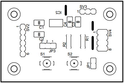
3.Component layout (note the dark 3 lines are for wire jumpers)
4. Assembled board (note 3wire jumpers as it is single side I could not avoid, 117 3.3V regulator is SMD and I do not have it right now so not soldered in bottom side. Later in the input side 10uF capacitor place I put a 2pin header so I can connect to an external regulator PCB module )


The breakout board will have reset button, GPIO0 ground button, a jumper to ground GPIO0, power selection jumper, a port with 3.3V, GND and GPIO2.
Give below my progress step by step:
1. Schematic
5. All boards connected together
6. Working one (note : as I have not soldered 3.3V regulator, still using external regulator module)
7. With 3.3V regulator soldered (during soldering I found out, I did a mistake in AM117 footprint, now I updated schematic and board to v1.1, I did a small track repair to make my v1.0 PCB work)
8. Check github for related files at https://github.com/MohanRenganathan/ESP8266-ESP-01
